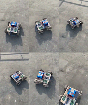
制作ROS小车系列(一)——小车底盘制作(麦科勒姆轮地盘)
目录
- 制作ROS小车系列(一)——小车底盘制作(麦科勒姆轮地盘)
- 一、制作前的材料准备
- 二、硬件的连线组装
- 三、底盘运动学的计算
- 四、底盘测试
一、制作前的材料准备
制作小车的材料准备主要包含底盘结构、硬件等详细清单如下:
1. 小车底盘结构件(制作车体的材料包含麦轮)
2. 四个带霍尔编码器的电机(根据小车大小来选择,建议电机带减速器的)
3. 两块直流电机驱动板(我的是10A桥式驱动板)
4. 两个或者三个降压模块(最好是带屏蔽的)
5. arduino mage2560一个
6. 继电器、开关一个
7. 24v锂电池一块
8. 连接线、杜邦线若干
二、硬件的连线组装
大家把自己的车子搭建好了以后就可以进行硬件的连线准备了,具体的接线如下图所示:

其中编码器的编号的电机的编号是对应的。编码器A、B相的接线对应在arduino板上的引脚我已经标注在上面了,值得注意的是编码器的A\B相是需要接在中断引脚上的,而arduino mage2560的中断引脚只有2、3、18、19、20、21共六个,如果直接连接是不够用的,所有我只把A相接到中断上,利用A相进行中断脉冲计数实现电机转速的测量。
三、底盘运动学的计算
1、麦轮的安装方法
麦轮有左旋和右旋轮的区别,这一点大家一定要搞清楚,不然最终会背离大家底盘控制的效果!

麦轮小车的轮子一共有四种安装方法,要想实现全向移动我们直接采用O-长方形的安装方式,也就是四个麦轮与地面接触的轮毂方向围成了一个圆形的仿蛇并且车底盘为矩形。如下图最后一种方式。

安装好了以后我们就可以开始进行底盘运动学的分析了
2、运动学分析
这部分有很多人已经写过相关的博客,我这里个大家推荐一个需要具体了解推到方法和过程的可以去具体了解一下。麦轮底盘运动学分析 我这里直接把最终的逆运动学方程给大家

上式中vty、vtx和omga分别为我们小车y向速度、x向速度、z轴的旋转角速度,这些是我们期望或者说给小车的量是已知的。左边的v为每一个车轮的旋转速度。
3、arduino的控制代码
我们将上面的运动学通过编程就可以实现对底盘的控制了,具体的代码如下:
//1,2号电机
#define DIR1 4
#define pwm1 5
#define DIR2 6
#define pwm2 7
#define motorcount1A 18 //编码器A 中断号:5
#define motorcount1B 14 //编码器B 中断号:4
#define motorcount2A 19 //编码器A 中断号:5
#define motorcount2B 15 //编码器B 中断号:4

//3,4号电机
#define DIR3 8
#define pwm3 9
#define DIR4 10
#define pwm4 11
#define motorcount3A 20 //编码器A 中断号:5
#define motorcount3B 16 //编码器B 中断号:4
#define motorcount4A 21 //编码器A 中断号:5
#define motorcount4B 17 //编码器B 中断号:4

#define TrgPin1 22  //超声波引脚定义
#define EcoPin1 23
#define TrgPin2 24
#define EcoPin2 25
#define TrgPin3 26
#define EcoPin3 27
#define TrgPin4 28
#define EcoPin4 29

volatile float motor1=0;//中断变量,左轮子脉冲计数
volatile float motor2=0;//中断变量,左轮子脉冲计数
volatile float motor3=0;//中断变量,左轮子脉冲计数
volatile float motor4=0;//中断变量,左轮子脉冲计数

float V_motor_1=0; //左轮速度 单位cm/s
float V_motor_2=0; //左轮速度 单位cm/s
float V_motor_3=0; //左轮速度 单位cm/s
float V_motor_4=0; //左轮速度 单位cm/s

int v1=0;  //单位cm/s
int v2=0;  //单位cm/s
int v3=0;  //单位cm/s
int v4=0;  //单位cm/s

float PotBuffer1 = 0;
float PotBuffer2 = 0;
float PotBuffer3 = 0;
float PotBuffer4 = 0;

float car_vx=0;
float car_vy=0;
float car_yaw=0;

char BluetoothData;
int PotBuffer = 0;
int omga=0;
int Dist[4];
int max_v=100;

void setup()
{
  Serial.begin(9600);
  pinMode(12,OUTPUT);
  pinMode(motorcount1A,INPUT); //左轮编码器A引脚
  pinMode(motorcount1B,INPUT); //左轮编码器B引脚

  //电机引脚定义
  pinMode(pwm1,OUTPUT);		//IO输出
  pinMode(pwm2,OUTPUT);		//IO输出
  pinMode(pwm3,OUTPUT);    //IO输出
  pinMode(pwm4,OUTPUT);
  digitalWrite(pwm1,LOW);	//pwm1引脚输出低电平,
  digitalWrite(pwm2,LOW);	//pwm2引脚输出低电平,
  digitalWrite(pwm3,LOW);  //pwm1引脚输出低电平,
  digitalWrite(pwm4,LOW);
  pinMode(DIR1,OUTPUT);		//IO输出
  pinMode(DIR2,OUTPUT);		//IO输出
  pinMode(DIR3,OUTPUT);    //IO输出
  pinMode(DIR4,OUTPUT);
  	//定义KEY2为带上拉输入引脚
  delay(100);
  digitalWrite(12,HIGH);
}


void read_motor_v()
{
  unsigned long nowtime=0;  //机时时间定义
  motor1=0;   //脉冲初始化
  motor2=0;
  motor3=0;
  motor4=0;

  nowtime=millis()+50;
  while(millis()<nowtime){
  attachInterrupt(digitalPinToInterrupt(motorcount1A),read_motor_1,RISING);  //子50ms内进行脉冲计数(调用中断函数)
  attachInterrupt(digitalPinToInterrupt(motorcount2A),read_motor_2,RISING);
  attachInterrupt(digitalPinToInterrupt(motorcount3A),read_motor_3,RISING);
  attachInterrupt(digitalPinToInterrupt(motorcount4A),read_motor_4,RISING);
  }

  detachInterrupt(digitalPinToInterrupt(motorcount1A));  //关闭中断计数
  detachInterrupt(digitalPinToInterrupt(motorcount2A));
  detachInterrupt(digitalPinToInterrupt(motorcount3A));
  detachInterrupt(digitalPinToInterrupt(motorcount4A));

  V_motor_1=((motor1/390)*15*PI*11.84)/0.05;   //根据脉冲数、时间、轮子打半径计算速度
  V_motor_2=((motor2/390)*6.5*PI)/0.05;
  V_motor_3=((motor3/390)*6.5*PI)/0.05;
  V_motor_4=((motor4/390)*6.5*PI)/0.05;
  Serial.print("速度:");
  //Serial.println(V_motor_1);
  v1=V_motor_1/1000;
  v2=V_motor_2;
  v3=V_motor_3;
  v4=V_motor_4;
}
void read_motor_1(){   //motor脉冲计数中断函数
  motor1++;
  //Serial.println(motor1);
}

void read_motor_2(){
  motor2++;
}

void read_motor_3(){
  motor3++;
}

void read_motor_4(){
  motor4++;
}
float a=360/2,b=265/2;

void generate_motor_v(float car_vx,float car_vy,float car_yaw)
{
  PotBuffer1 = car_vx-car_vy+car_yaw*(a+b);
  PotBuffer2 = car_vx+car_vy-car_yaw*(a+b);
  PotBuffer3 = car_vx-car_vy-car_yaw*(a+b);
  PotBuffer4 = car_vx+car_vy+car_yaw*(a+b);

  if(PotBuffer1>=max_v)PotBuffer1=max_v;
  else if(PotBuffer1<-max_v)PotBuffer1=-max_v;

  if(PotBuffer2>=max_v)PotBuffer2=max_v;
  else if(PotBuffer2<-max_v)PotBuffer2=-max_v;

  if(PotBuffer3>=max_v)PotBuffer3=max_v;
  else if(PotBuffer3<-max_v)PotBuffer3=-max_v;

  if(PotBuffer4>=max_v)PotBuffer4=max_v;
  else if(PotBuffer4<-max_v)PotBuffer4=-max_v;
}

void loop()
{
  if (Serial.available()){
    BluetoothData=Serial.read(); //Get next character from bluetooth
   }
   //**** Control Pad on Right -  Sends 'X__,Y___*' every 150ms
    if(BluetoothData=='R'){
      PotBuffer=Serial.parseInt();
      while (BluetoothData!='*'){
        if (Serial.available()){
          BluetoothData=Serial.read(); //Get next character from bluetooth
          if(BluetoothData=='A')
          {
            omga=Serial.parseInt();
            omga=omga*PI/180;
          }
        }
      }
      car_vx=PotBuffer*cos(omga);
      car_vy=-PotBuffer*sin(omga);
      car_vx=map(car_vx,0,10,0,max_v);
      car_vy=map(car_vy,0,10,0,max_v);
    }
    if(BluetoothData=='X')
    {
      int pad_x=Serial.parseInt();
      int pad_y=0;
      while (BluetoothData!='*'){
        if (Serial.available()){
          BluetoothData=Serial.read(); //Get next character from bluetooth
          if(BluetoothData=='Y')pad_y=Serial.parseInt();
        }
      }
      car_yaw=sqrt(pad_x*pad_x+pad_y*pad_y);
      if(pad_x>=0)car_yaw=car_yaw;
      else if(pad_x<0)car_yaw=-car_yaw;
    }
    if(BluetoothData=='a')
    {
      max_v=50;
      Serial.print("max_v:");
      Serial.println(max_v);
    }
    if(BluetoothData=='b')
    {
      max_v=100;
      Serial.print("max_v:");
      Serial.println(max_v);
    }
    if(BluetoothData=='c')
    {
      max_v=150;
      Serial.print("max_v:");
      Serial.println(max_v);
    }

    generate_motor_v(car_vx,car_vy,car_yaw);    //已知希望的小车运动速度产生四个电机的转速
    if(PotBuffer1>=0)digitalWrite(DIR1,LOW);    //一下部分为控制电机的转向,<0反向
    else if(PotBuffer1<0)digitalWrite(DIR1,HIGH);
    if(PotBuffer2>=0)digitalWrite(DIR2,HIGH);
    else if(PotBuffer2<0)digitalWrite(DIR2,LOW);
    if(PotBuffer3>=0)digitalWrite(DIR3,HIGH);
    else if(PotBuffer3<0)digitalWrite(DIR3,LOW);
    if(PotBuffer4>=0)digitalWrite(DIR4,LOW);
    else if(PotBuffer4<0)digitalWrite(DIR4,HIGH);

  if(PotBuffer>max_v)PotBuffer=max_v;
  else if(PotBuffer<-max_v)PotBuffer=-max_v;

  read_motor_v();
//  Serial.print("sudu");
  Serial.println(v1);
  analogWrite(pwm1,0);
  analogWrite(pwm2,10);
  analogWrite(pwm3,abs(PotBuffer3));
  analogWrite(pwm4,abs(PotBuffer4));

  //Serial.println(PotBuffer);
  //delay(50);
}
为了使大家可以更好的理解代码的结构的对代码进行简单的说明。
#define DIR1 4
#define pwm1 5
#define DIR2 6
#define pwm2 7
#define motorcount1A 18 //编码器A 中断号:5
#define motorcount1B 14 //编码器B 中断号:4
#define motorcount2A 19 //编码器A 中断号:5
#define motorcount2B 15 //编码器B 中断号:4

//3,4号电机
#define DIR3 8
#define pwm3 9
#define DIR4 10
#define pwm4 11
#define motorcount3A 20 //编码器A 中断号:5
#define motorcount3B 16 //编码器B 中断号:4
#define motorcount4A 21 //编码器A 中断号:5
#define motorcount4B 17 //编码器B 中断号:4

#define TrgPin1 22  //超声波引脚定义
#define EcoPin1 23
#define TrgPin2 24
#define EcoPin2 25
#define TrgPin3 26
#define EcoPin3 27
#define TrgPin4 28
#define EcoPin4 29
这部分是对我们的电机控制引脚和编码器的控制引脚的定义,这部分大家可以对照一下上面的硬件路线部分。
下面这部分代码是编码器读取电机速度的程序,其原理就是利用arduino中断引脚,规定一定的时间段(如50ms),在这段时间内触发中断,利用编码器对电机脉冲进行计数,然后通过与编码器转一圈的固定脉冲进行对比来判断电机转了多少圈进而计算出电机的转速。
void read_motor_v()
{
  unsigned long nowtime=0;  //机时时间定义
  motor1=0;   //脉冲初始化
  motor2=0;
  motor3=0;
  motor4=0;

  nowtime=millis()+50;
  while(millis()<nowtime){
  attachInterrupt(digitalPinToInterrupt(motorcount1A),read_motor_1,RISING);  //子50ms内进行脉冲计数(调用中断函数)
  attachInterrupt(digitalPinToInterrupt(motorcount2A),read_motor_2,RISING);
  attachInterrupt(digitalPinToInterrupt(motorcount3A),read_motor_3,RISING);
  attachInterrupt(digitalPinToInterrupt(motorcount4A),read_motor_4,RISING);
  }

  detachInterrupt(digitalPinToInterrupt(motorcount1A));  //关闭中断计数
  detachInterrupt(digitalPinToInterrupt(motorcount2A));
  detachInterrupt(digitalPinToInterrupt(motorcount3A));
  detachInterrupt(digitalPinToInterrupt(motorcount4A));

  V_motor_1=((motor1/390)*15*PI*11.84)/0.05;   //根据脉冲数、时间、轮子打半径计算速度
  V_motor_2=((motor2/390)*6.5*PI)/0.05;
  V_motor_3=((motor3/390)*6.5*PI)/0.05;
  V_motor_4=((motor4/390)*6.5*PI)/0.05;
  Serial.print("速度:");
  //Serial.println(V_motor_1);
  v1=V_motor_1/1000;
  v2=V_motor_2;
  v3=V_motor_3;
  v4=V_motor_4;
}
以下这部分代码就是我们小车的底盘逆运动学,已知小车运动的vx、vy、zomga求四个电机的转速。
void generate_motor_v(float car_vx,float car_vy,float car_yaw)
{
  PotBuffer1 = car_vx-car_vy+car_yaw*(a+b);
  PotBuffer2 = car_vx+car_vy-car_yaw*(a+b);
  PotBuffer3 = car_vx-car_vy-car_yaw*(a+b);
  PotBuffer4 = car_vx+car_vy+car_yaw*(a+b);

  if(PotBuffer1>=max_v)PotBuffer1=max_v;
  else if(PotBuffer1<-max_v)PotBuffer1=-max_v;

  if(PotBuffer2>=max_v)PotBuffer2=max_v;
  else if(PotBuffer2<-max_v)PotBuffer2=-max_v;

  if(PotBuffer3>=max_v)PotBuffer3=max_v;
  else if(PotBuffer3<-max_v)PotBuffer3=-max_v;

  if(PotBuffer4>=max_v)PotBuffer4=max_v;
  else if(PotBuffer4<-max_v)PotBuffer4=-max_v;
}
由于该代码是用蓝牙来控制小车底盘的,所有一下这部分代码是实现对小车的蓝牙控制,其本质是读取蓝牙的串口命令并对命令进行判断。
if (Serial.available()){
    BluetoothData=Serial.read(); //Get next character from bluetooth
   }
   //**** Control Pad on Right -  Sends 'X__,Y___*' every 150ms
    if(BluetoothData=='R'){
      PotBuffer=Serial.parseInt();
      while (BluetoothData!='*'){
        if (Serial.available()){
          BluetoothData=Serial.read(); //Get next character from bluetooth
          if(BluetoothData=='A')
          {
            omga=Serial.parseInt();
            omga=omga*PI/180;
          }
        }
      }
      car_vx=PotBuffer*cos(omga);
      car_vy=-PotBuffer*sin(omga);
      car_vx=map(car_vx,0,10,0,max_v);
      car_vy=map(car_vy,0,10,0,max_v);
}代码部分的介绍就到这里,大家如果还有不懂的可以留言讨论!
四、底盘测试
完成以上部分我们基本上就可以用蓝牙设备(如手机)实现我们小车的全向移动控制了,也算是迈出了万里长征的第一步!!!
测试结果如下:

这部分完成测试没问题以后,接下来我们就可以开始我们上位机的准备和导航之旅了!!!!


