简 介: 本文给出了对于ESP32开发板下载相关的MicroPython,使用Thony编程环境完成对于ESP32开发板的一些基础实验。详细的实验命令解释可以结合MicroPython的官方网站。关键词: ESP32,MicroPython
▌01 ESP32开发板 MicroPython
1.ESP32开发板
在 给出了ESP32的一些基本实验 记录的是从 ESP32开发板\购买的开发板。而这次是从 巨人电子科技 购买到的开发板。 现在刚刚到货,下面对它进行初步的测试。

▲ 刚刚到货的ESP32开发板
虽然前面的13.88已经够便宜了,但是在下面 ESP8266串口wifi模块 V3 物联网 开发板 CH-340 网站则出售¥10左右的模块。但是并没有特别标志出是否能够使用MicroPython。现在已经下单购买两块进行测试。
2.焊接ESP32引脚
(1)ESP管脚定义

▲ ESP32 管脚定义
(2)焊接管脚之后的ESP32模块

▲ 焊接管脚之后的ESP32模块
3.下载ESP32固件
(1)下载ESP32 固件
从 MicroPython - Python for microcontrollers 下载:GENERIC : esp32-20210325-unstable-v1.14-121-g4fc2866f4.bin 。
(2)接入ESP32
接入ESP32到USB端口之后出现的虚拟串口:

▲ 接入ESP32到USB端口之后出现的虚拟串口
(3)配置Thonny解释器
依靠 Thonny Python开发环境 下载ESP32固件。首先配置Thonny的ESP32解释器。

▲ Thonny配置ESP32解释器
对于ESP32一开始的固件,在连接Thonny的时候会出现错误。如下图所示:

▲ 一开始Thonny连接出现错误
(4)下载ESP32固件
通过ESP32的Firmware Installer来讲前面刚刚下载之后的ESP32的固件烧录到ESP32的模块中。这个过程所需要的时间比较多一些。

▲ 使用Thonny下载ESP32 固件
在刷新ESP32之后,再使用Thonny连接ESP32,就会出下下面REPL的信息。

▲ 下载完ESP32固件之后Thonny连接效果
刚刚连接之后在Thonny的Shell窗口出现的信息:
ets Jun  8 2016 00:22:57

rst:0x1 (POWERON_RESET),boot:0x13 (SPI_FAST_FLASH_BOOT)
configsip: 0, SPIWP:0xee
clk_drv:0x00,q_drv:0x00,d_drv:0x00,cs0_drv:0x00,hd_drv:0x00,wp_drv:0x00
mode:DIO, clock div:2
load:0x3fff0030,len:4
load:0x3fff0034,len:5636
load:0x40078000,len:12696
load:0x40080400,len:4292
entry 0x400806b0
MicroPython v1.14 on 2021-03-25; ESP32 module with ESP32
Type "help()" for more information.
MicroPython v1.14 on 2021-03-25; ESP32 module with ESP32

Type "help()" for more information.
使用help()命令获得ESP32的基本信息。
Welcome to MicroPython on the ESP32!

For generic online docs please visit http://docs.micropython.org/

For access to the hardware use the 'machine' module:

import machine
pin12 = machine.Pin(12, machine.Pin.OUT)
pin12.value(1)
pin13 = machine.Pin(13, machine.Pin.IN, machine.Pin.PULL_UP)
print(pin13.value())
i2c = machine.I2C(scl=machine.Pin(21), sda=machine.Pin(22))
i2c.scan()
i2c.writeto(addr, b'1234')
i2c.readfrom(addr, 4)

Basic WiFi configuration:

import network
sta_if = network.WLAN(network.STA_IF); sta_if.active(True)
sta_if.scan()                             # Scan for available access points
sta_if.connect("<AP_name>", "<password>") # Connect to an AP
sta_if.isconnected()                      # Check for successful connection

Control commands:
  CTRL-A        -- on a blank line, enter raw REPL mode
  CTRL-B        -- on a blank line, enter normal REPL mode
  CTRL-C        -- interrupt a running program
  CTRL-D        -- on a blank line, do a soft reset of the board
  CTRL-E        -- on a blank line, enter paste mode

For further help on a specific object, type help(obj)
For a list of available modules, type help('modules')
通过前面的测试,可以验证从巨人电子科技购买到的比较偏移的模块能够满足基本的操作。
▌02 ESP32的基本实验
对于ESP32的开发可以参见 Quick reference for the ESP32
1.General Board Control
(1)machine.freq()
显示模块的工作频率,然后设置对应的frequency。
import machine
print(machine.freq())
machine.freq(240000000)
print(machine.freq())
下面是运行结果输出。可以看到模块开始的频率为160MHz,设置之后编程了240MHz.
>>> %Run -c $EDITOR_CONTENT
160000000
240000000
>>> %Run -c $EDITOR_CONTENT
240000000
240000000
(2)Flash
import machine
import esp
print(esp.flash_size())
print(esp.flash_user_start())
4194304
2097152关于内部的Flash读写的实验,可以参见 ESP32模块的MicroPython的基本实验 中给出的测试结果。
2.Sensor
(1)HALL
import machine
import esp32
import time
while True:
    data = [esp32.hall_sensor() for _ in range(256)]
    print(sum(data)/len(data))
    time.sleep_ms(100)
▲ 使用磁铁来影响HALL的输出
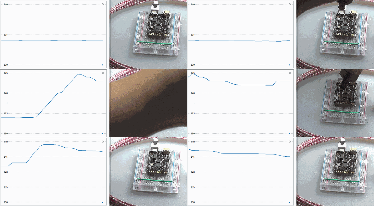
(2)Temperature
import machine
import esp32
import time
while True:
    data = [esp32.raw_temperature() for _ in range(256)]
    print(sum(data)/len(data))
    time.sleep_ms(100)
▲ 对于ESP32芯片加热可以改变内部温度输出数值
3. Timers & Pins
from machine                import Pin
import time
p0 = Pin(0, Pin.OUT)
while True:
    p0.on()
    time.sleep_ms(25)
    p0.off()
    time.sleep_ms(25)
▲ ESP32模块的管教分布

▲ PIn0输出的波形
4.DAC
DAC可以从Pin.25, Pin 26输出。DAC的范围 0 ~ 255。
from machine                import Pin
import time
from machine                import DAC
dac = DAC(Pin(25))
while True:
    dac.write(0)
    time.sleep_ms(25)
    dac.write(255)
    time.sleep_ms(25)
▲ 从PIN25输出的电压波形
5. ADC
On the ESP32 ADC functionality is available on Pins 32-39. Note that, when using the default configuration, input voltages on the ADC pin must be between 0.0v and 1.0v (anything above 1.0v will just read as 4095). Attenuation must be applied in order to increase this usable voltage range.
(1)直接读取数值

▲ DAC输出与ADC采集数值
from machine                import Pin
import time
from machine                import DAC,ADC
dac = DAC(Pin(25))
adc = ADC(Pin(32))
readdim = []
for i in range(256):
    dac.write(i)
    time.sleep_ms(10)
    readdim.append(adc.read())
print(readdim)
▲ 采集16个点平均之后的读数

▲ 衰减6db之后的DAC与ADC
(2)ADC输入衰减
将输入衰减11dB,对应的衰减倍数为:
from machine                import Pin
import time
from machine                import DAC,ADC
dac = DAC(Pin(25))
adc = ADC(Pin(32))
adc.atten(ADC.ATTN_11DB)
readdim = []
for i in range(256):
    dac.write(i)
    time.sleep_ms(10)
    dim = [adc.read() for _ in range(16)]
    readdim.append(sum(dim) / len(dim))
print(readdim)
▲ 输入衰减11db采集的数据
- ADC.ATTN_0DB: 0dB attenuation, gives a maximum input voltage of 1.00v - this is the default configuration
- ADC.ATTN_2_5DB: 2.5dB attenuation, gives a maximum input voltage of approximately 1.34v
- ADC.ATTN_6DB: 6dB attenuation, gives a maximum input voltage of approximately 2.00v
- ADC.ATTN_11DB: 11dB attenuation, gives a maximum input voltage of approximately 3.6v
(3)分辨率为9BIT
from machine                import Pin
import time
from machine                import DAC,ADC
dac = DAC(Pin(25))
adc = ADC(Pin(32))
adc.atten(ADC.ATTN_11DB)
adc.width(ADC.WIDTH_9BIT)
readdim = []
for i in range(256):
    dac.write(i)
    time.sleep_ms(10)
    dim = [adc.read() for _ in range(16)]
    readdim.append(sum(dim) / len(dim))
print(readdim)
▲ 分辨率为9BIT
(4)测试DAC的线性
a.读取输入
from machine                import DAC
import sys
from machine                import Pin
dac = DAC(Pin(25))
while True:
    nb = input('Choose a number: ')
    dac.write(int(nb))
b.测量输出

▲ DAC输出数值
from tsmodule.tsvisa        import *
from tsmodule.tsstm32       import *
thonny_title = 'Thonny'
def thonnycmd(cmd):
    tspsendwindowkey(thonny_title, 's', alt=1)
    tspsendwindowkey(thonny_title, '%s\r'%cmd)
vdim = []
for i in range(256):
    thonnycmd('%d'%i)
    time.sleep(1)
    meter = meterval()
    vdim.append(meter[0])
    printff(i, meter[0])
    tspsave('measure', v=vdim)
plt.plot(vdim)
plt.xlabel("n")
plt.ylabel("v")
plt.grid(True)
plt.tight_layout()
plt.show()
6.PWM
测试代码:
from machine                import PWM, Pin
pwm0 = PWM(Pin(0))
print(pwm0.freq())
pwm0.freq(1000)
print(pwm0.duty())
pwm0.duty(200)
运行结果:
>>> %Run -c $EDITOR_CONTENT
5000
512
▲ 设置duty为 200输出的PWM波形
如果驱动舵机,需要设置PWM的频率为50Hz(周期:20ms),输出1.5ms;对应duty=77.
从1.0ms变化到2ms,对应的duty:51 - 102。

▲ 输出50Hz舵机驱动波形

▲ 输出 1.5ms的波形
▌实验总结
针对购买到的ESP32模块进行部分的实验,为将来基于该模块的实验提供基础。
■ 相关文献链接:
- ESP32模块的MicroPython的基本实验
- 淘宝ESP32开发板
- 巨人电子科技
- ESP8266串口wifi模块 V3 物联网 开发板 CH-340-淘宝网
- 两款带有WiFI的MicroPython模块:ESP32,ESP8266
- MicroPython - Python for microcontrollers
- esp32-20210325-unstable-v1.14-121-g4fc2866f4.bin
- 安装 Thonny 软件环境开发PI Pico
- Quick reference for the ESP32


