
程序员很难有机会接触到底层的一些东西,尤其是偏硬件部分,所以记录下
光纤和普通网线的性能差异
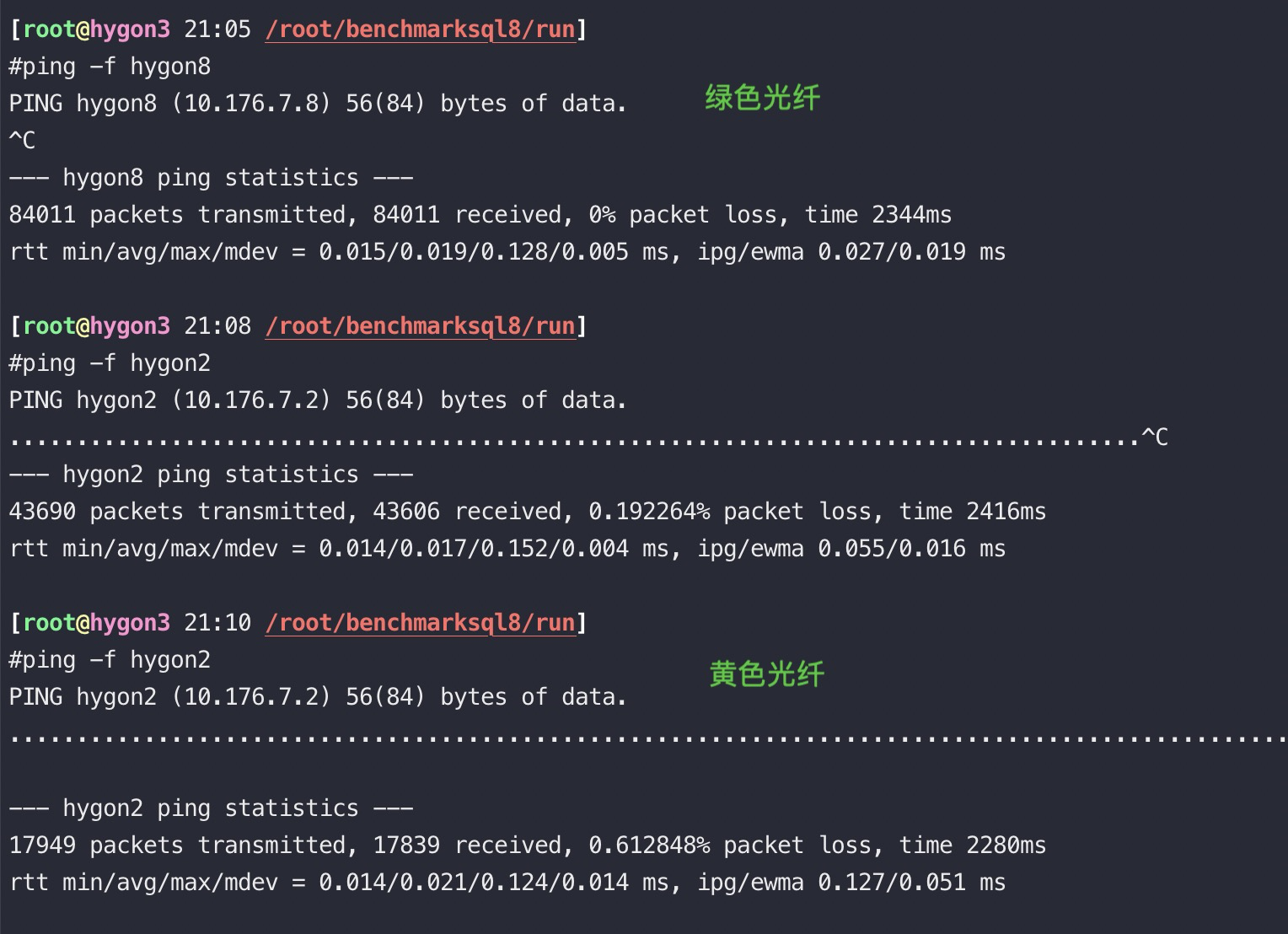
以下都是在4.19内核的UOS,光纤交换机为锐捷,服务器是华为鲲鹏920的环境测试所得数据:
![[转帖]网络硬件相关知识_网线](https://s2.51cto.com/images/blog/202404/20015144_6622af30601717101.png?x-oss-process=image/watermark,size_16,text_QDUxQ1RP5Y2a5a6i,color_FFFFFF,t_30,g_se,x_10,y_10,shadow_20,type_ZmFuZ3poZW5naGVpdGk= "image.png")
光纤稳定性好很多,平均rt是网线的三分之一,最大值则是网线的十分之一. 上述场景下光纤的带宽大约是网线的1.5倍. 实际光纤理论带宽一般都是万M, 网线是千M.
光纤接口:
![[转帖]网络硬件相关知识_网线_02](https://plantegg.github.io/images/oss/b67715de1b8e143f6fc17ba574bcf0c4.png "image.png")
单模光纤和多模光纤
下图绿色是多模光纤(Multi Mode Fiber),黄色是单模光纤(Single Mode Fiber), 因为光纤最好能和光模块匹配, 我们测试用的光模块都是多模的, 单模光纤线便宜,但是对应的光模块贵多了。
多模光模块工作波长为850nm,单模光模块工作波长为1310nm或1550nm, 从成本上来看,单模光模块所使用的设备多出多模光模块两倍,总体成本远高于多模光模块,但单模光模块的传输距离也要长于多模光模块,单模光模块最远传输距离为100km,多模光模块最远传输距离为2km。因单模光纤的传输原理为使光纤直射到中心,所以主要用作远距离数据传输,而多模光纤则为多通路传播模式,所以主要用于短距离数据传输。单模光模块适用于对距离和传输速率要求较高的大型网络中,多模光模块主要用于短途网路。
ping结果比较:
[aliyun@uos15 11:00 /home/aliyun] 以下88都是光口、89都是电口。
$ping -c 10 10.88.88.16 //光纤
PING 10.88.88.16 (10.88.88.16) 56(84) bytes of data.
64 bytes from 10.88.88.16: icmp_seq=1 ttl=64 time=0.058 ms
64 bytes from 10.88.88.16: icmp_seq=2 ttl=64 time=0.049 ms
64 bytes from 10.88.88.16: icmp_seq=3 ttl=64 time=0.053 ms
64 bytes from 10.88.88.16: icmp_seq=4 ttl=64 time=0.040 ms
64 bytes from 10.88.88.16: icmp_seq=5 ttl=64 time=0.053 ms
64 bytes from 10.88.88.16: icmp_seq=6 ttl=64 time=0.043 ms
64 bytes from 10.88.88.16: icmp_seq=7 ttl=64 time=0.038 ms
64 bytes from 10.88.88.16: icmp_seq=8 ttl=64 time=0.050 ms
64 bytes from 10.88.88.16: icmp_seq=9 ttl=64 time=0.043 ms
64 bytes from 10.88.88.16: icmp_seq=10 ttl=64 time=0.064 ms

--- 10.88.88.16 ping statistics ---
10 packets transmitted, 10 received, 0% packet loss, time 159ms
rtt min/avg/max/mdev = 0.038/0.049/0.064/0.008 ms

[aliyun@uos15 11:01 /home/aliyun]
$ping -c 10 10.88.89.16 //电口
PING 10.88.89.16 (10.88.89.16) 56(84) bytes of data.
64 bytes from 10.88.89.16: icmp_seq=1 ttl=64 time=0.087 ms
64 bytes from 10.88.89.16: icmp_seq=2 ttl=64 time=0.053 ms
64 bytes from 10.88.89.16: icmp_seq=3 ttl=64 time=0.095 ms
64 bytes from 10.88.89.16: icmp_seq=4 ttl=64 time=0.391 ms
64 bytes from 10.88.89.16: icmp_seq=5 ttl=64 time=0.051 ms
64 bytes from 10.88.89.16: icmp_seq=6 ttl=64 time=0.343 ms
64 bytes from 10.88.89.16: icmp_seq=7 ttl=64 time=0.045 ms
64 bytes from 10.88.89.16: icmp_seq=8 ttl=64 time=0.341 ms
64 bytes from 10.88.89.16: icmp_seq=9 ttl=64 time=0.054 ms
64 bytes from 10.88.89.16: icmp_seq=10 ttl=64 time=0.066 ms

--- 10.88.89.16 ping statistics ---
10 packets transmitted, 10 received, 0% packet loss, time 149ms
rtt min/avg/max/mdev = 0.045/0.152/0.391/0.136 ms

[aliyun@uos15 11:02 /u01]
$scp uos.tar aliyun@10.88.89.16:/tmp/
uos.tar 100% 3743MB 111.8MB/s 00:33

[aliyun@uos15 11:03 /u01]
$scp uos.tar aliyun@10.88.88.16:/tmp/
uos.tar 100% 3743MB 178.7MB/s 00:20

[aliyun@uos15 11:07 /u01]
$sudo ping -f 10.88.89.16
PING 10.88.89.16 (10.88.89.16) 56(84) bytes of data.
--- 10.88.89.16 ping statistics ---
284504 packets transmitted, 284504 received, 0% packet loss, time 702ms
rtt min/avg/max/mdev = 0.019/0.040/1.014/0.013 ms, ipg/ewma 0.048/0.042 ms

[aliyun@uos15 11:07 /u01]
$sudo ping -f 10.88.88.16
PING 10.88.88.16 (10.88.88.16) 56(84) bytes of data.
--- 10.88.88.16 ping statistics ---
299748 packets transmitted, 299748 received, 0% packet loss, time 242ms
rtt min/avg/max/mdev = 0.012/0.016/0.406/0.006 ms, pipe 2, ipg/ewma 0.034/0.014 ms
多网卡bonding
#cat ifcfg-bond0
DEVICE=bond0
TYPE=Bond
ONBOOT=yes
BOOTPROTO=static
IPADDR=10.176.7.11
NETMASK=255.255.255.0

#cat /etc/sysconfig/network-scripts/ifcfg-eth0
DEVICE=eth0
TYPE=Ethernet
ONBOOT=yes
BOOTPROTO=none
MASTER=bond0
SLAVE=yes

#cat /etc/sysconfig/network-scripts/ifcfg-eth1
DEVICE=eth1
TYPE=Ethernet
ONBOOT=yes
BOOTPROTO=none
MASTER=bond0
SLAVE=yes

#cat /proc/net/bonding/bond0

----加载内核bonding模块, mode=0 是RR负载均衡模式
#cat /etc/modprobe.d/bonding.conf
# modprobe bonding
alias bond0 bonding
options bond0 mode=0 miimon=100 //这一行也可以放到bond0配置文件中,比如:BONDING_OPTS="miimon=100 mode=4 xmit_hash_policy=layer3+4" 用iperf 多连接测试bonding后的带宽发现,发送端能用上两张网卡,但是接收队列只能使用一张物理网卡
网卡绑定mode共有七种(0~6) bond0、bond1、bond2、bond3、bond4、bond5、bond6
常用的有三种
- mode=0:平衡负载模式 (balance-rr),有自动备援,两块物理网卡和bond网卡使用同一个mac地址,但需要”Switch”支援及设定。
- mode=1:自动备援模式 (balance-backup),其中一条线若断线,其他线路将会自动备援。
- mode=6:平衡负载模式(balance-alb),有自动备援,不必”Switch”支援及设定,两块网卡是使用不同的MAC地址
- Mode 4 (802.3ad): This mode creates aggregation groups that share the same speed and duplex settings, and it requires a switch that supports an IEEE 802.3ad dynamic link. Mode 4 uses all interfaces in the active aggregation group. For example, you can aggregate three 1 GB per second (GBPS) ports into a 3 GBPS trunk port. This is equivalent to having one interface with 3 GBPS speed. It provides fault tolerance and load balancing.
需要说明的是如果想做成mode 0的负载均衡,仅仅设置这里options bond0 miimon=100 mode=0是不够的,与网卡相连的交换机必须做特殊配置(这两个端口应该采取聚合方式),因为做bonding的这两块网卡是使用同一个MAC地址.从原理分析一下(bond运行在mode 0下):
mode 0下bond所绑定的网卡的IP都被修改成相同的mac地址,如果这些网卡都被接在同一个交换机,那么交换机的arp表里这个mac地址对应的端口就有多 个,那么交换机接受到发往这个mac地址的包应该往哪个端口转发呢?正常情况下mac地址是全球唯一的,一个mac地址对应多个端口肯定使交换机迷惑了。所以 mode0下的bond如果连接到交换机,交换机这几个端口应该采取聚合方式(cisco称为 ethernetchannel,foundry称为portgroup),因为交换机做了聚合后,聚合下的几个端口也被捆绑成一个mac地址.我们的解决办法是,两个网卡接入不同的交换机即可。
mode6模式下无需配置交换机,因为做bonding的这两块网卡是使用不同的MAC地址。
mod=5,即:(balance-tlb) Adaptive transmit load balancing(适配器传输负载均衡)
特点:不需要任何特别的switch(交换机)支持的通道bonding。在每个slave上根据当前的负载(根据速度计算)分配外出流量。如果正在接受数据的slave出故障了,另一个slave接管失败的slave的MAC地址。
该模式的必要条件:ethtool支持获取每个slave的速率.
案例,两块万兆bonding后带宽翻倍
#ethtool bond0
Settings for bond0:
Supported ports: [ ]
Supported link modes: Not reported
Supported pause frame use: No
Supports auto-negotiation: No
Advertised link modes: Not reported
Advertised pause frame use: No
Advertised auto-negotiation: No
Speed: 20000Mb/s
Duplex: Full
Port: Other
PHYAD: 0
Transceiver: internal
Auto-negotiation: off
Link detected: yes

[root@phy 16:55 /root]
#cat /etc/sysconfig/network-scripts/ifcfg-bond0
DEVICE=bond0
BOOTPROTO=static
TYPE="ethernet"
IPADDR=100.1.1.2
NETMASK=255.255.255.192
ONBOOT=yes
USERCTL=no
PEERDNS=no
BONDING_OPTS="miimon=100 mode=4 xmit_hash_policy=layer3+4"

#cat /etc/modprobe.d/bonding.conf
alias netdev-bond0 bonding

#lsmod |grep bond
bonding 137339 0

#cat ifcfg-bond0
DEVICE=bond0
BOOTPROTO=static
TYPE="ethernet"
IPADDR=100.81.131.221
NETMASK=255.255.255.192
ONBOOT=yes
USERCTL=no
PEERDNS=no
BONDING_OPTS="miimon=100 mode=4 xmit_hash_policy=layer3+4"

#cat ifcfg-eth1
DEVICE=eth1
TYPE="Ethernet"
HWADDR=7C:D3:0A:E0:F7:81
BOOTPROTO=none
ONBOOT=yes
MASTER=bond0
SLAVE=yes
PEERDNS=no
RX_MAX=`ethtool -g "$DEVICE" | grep 'Pre-set' -A1 | awk '/RX/{print $2}'`
RX_CURRENT=`ethtool -g "$DEVICE" | grep "Current" -A1 | awk '/RX/{print $2}'`
[[ "$RX_CURRENT" -lt "$RX_MAX" ]] && ethtool -G "$DEVICE" rx "$RX_MAX"
网络中断和绑核
网络包的描述符的内存(RingBuffer)跟着设备走(设备在哪个Die/Node上,就近分配内存), 数据缓冲区(Data Buffer–存放网络包)内存跟着队列(中断)走, 如果队列绑定到DIE0, 而设备在die1上,这样在做DMA通信时, 会产生跨die的交织访问。
不管设备插在哪一个die上, 只要描述符申请的内存和数据缓冲区的内存都在同一个die上(需要修改驱动源代码–非常规),就能避免跨die内存交织, 性能能保持一致。
irqbalance服务不会将中断进行跨node迁移,只会在同一numa node中进行优化。
ethtool
#ethtool -i p1p1 //查询网卡bus-info
driver: mlx5_core
version: 5.0-0
firmware-version: 14.27.1016 (MT_2420110004)
expansion-rom-version:
bus-info: 0000:21:00.0
supports-statistics: yes
supports-test: yes
supports-eeprom-access: no
supports-register-dump: no
supports-priv-flags: yes

//根据bus-info找到中断id
#cat /proc/interrupts | grep 0000:21:00.0 | awk -F: '{print $1}' | wc -l

//修改网卡队列数
sudo ethtool -L eth0 combined 2 (不能超过网卡最大队列数)

然后检查是否生效了(不需要重启应用和机器,实时生效):
sudo ethtool -l eth0
根据网卡bus-info可以找到对应的irq id
手工绑核脚本:
#!/bin/bash
#irq_list=(`cat /proc/interrupts | grep enp131s0 | awk -F: '{print $1}'`)
intf=$1
irq_list=(cat /proc/interrupts | grep `ethtool -i $intf |grep bus-info | awk '{ print $2 }'` | awk -F: '{print $1}')
cpunum=48 # 修改为所在node的第一个Core
for irq in ${irq_list[@]}
do
echo $cpunum > /proc/irq/$irq/smp_affinity_list
echo `cat /proc/irq/$irq/smp_affinity_list`
(( cpunum+=1 ))
done
检查绑定结果: sh irqCheck.sh enp131s0
# 网卡名
intf=$1
irqID=`ethtool -i $intf |grep bus-info | awk '{ print $2 }'`
log=irqSet-`date "+%Y%m%d-%H%M%S"`.log
# 可用的CPU数
cpuNum=$(cat /proc/cpuinfo |grep processor -c)
# RX TX中断列表
irqListRx=$(cat /proc/interrupts | grep ${irqID} | awk -F':' '{print $1}')
irqListTx=$(cat /proc/interrupts | grep ${irqID} | awk -F':' '{print $1}')
# 绑定接收中断rx irq
for irqRX in ${irqListRx[@]}
do
cat /proc/irq/${irqRX}/smp_affinity_list
done
# 绑定发送中断tx irq
for irqTX in ${irqListTx[@]}
do
cat /proc/irq/${irqTX}/smp_affinity_list
done
中断联合(Coalescing)
中断联合可供我们推迟向内核通告新事件的操作,将多个事件汇总在一个中断中通知内核。该功能的当前设置可通过ethtool -c查看:
$ ethtool -c eth0
Coalesce parameters for eth0:
...
rx-usecs: 50
tx-usecs: 50此处可以设置固定上限,对每内核每秒处理中断数量的最大值进行硬性限制,或针对特定硬件根据吞吐率自动调整中断速率。
启用联合(使用-C)会增大延迟并可能导致丢包,因此对延迟敏感的工作可能需要避免这样做。另外,彻底禁用该功能可能导致中断受到节流限制,进而影响性能。
多次在nginx场景下测试未发现这个值对TPS有什么明显的改善
How to achieve low latency with 10Gbps Ethernet 中有提到 Linux 3.11 added support for the SO_BUSY_POLL. 也有类似的作用
irqbalance
irqbalance 是一个命令行工具,在处理器中分配硬件中断以提高系统性能。默认设置下在后台程序运行,但只可通过 --oneshot 选项运行一次。
以下参数可用于提高性能。
- –powerthresh
CPU 进入节能模式之前,设定可空闲的 CPU 数量。如果有大于阀值数量的 CPU 是大于一个标准的偏差,该差值低于平均软中断工作负载,以及没有 CPU 是大于一个标准偏差,且该偏差高出平均,并有多于一个的 irq 分配给它们,一个 CPU 将处于节能模式。在节能模式中,CPU 不是 irqbalance 的一部分,所以它在有必要时才会被唤醒。 - –hintpolicy
决定如何解决 irq 内核关联提示。有效值为exact(总是应用 irq 关联提示)、subset(irq 是平衡的,但分配的对象是关联提示的子集)、或者ignore(irq 完全被忽略)。 - –policyscript
通过设备路径、当作参数的irq号码以及 irqbalance 预期的零退出代码,定义脚本位置以执行每个中断请求。定义的脚本能指定零或多键值对来指导管理传递的 irq 中 irqbalance。下列是为效键值对:ban有效值为true(从平衡中排除传递的 irq)或false(该 irq 表现平衡)。balance_level允许用户重写传递的 irq 平衡度。默认设置下,平衡度基于拥有 irq 设备的 PCI 设备种类。有效值为none、package、cache、或core。numa_node允许用户重写视作为本地传送 irq 的 NUMA 节点。如果本地节点的信息没有限定于 ACPI ,则设备被视作与所有节点距离相等。有效值为识别特定 NUMA 节点的整数(从0开始)和-1,规定 irq 应被视作与所有节点距离相等。 - –banirq
将带有指定中断请求号码的中断添加至禁止中断的列表。
也可以使用 IRQBALANCE_BANNED_CPUS 环境变量来指定被 irqbalance 忽略的 CPU 掩码。
//默认irqbalance绑定一个numa, -1指定多个numa
echo -1 >/sys/bus/pci/devices/`ethtool -i p1p1 |grep bus-info | awk '{ print $2 }'`/numa_node ;
// 目录 /sys/class/net/p1p1/ link到了 /sys/bus/pci/devices/`ethtool -i p1p1 |grep bus-info | awk '{ print $2 }'`

执行 irqbalance --debug 进行调试
irqbalance指定core
cat /etc/sysconfig/irqbalance
# IRQBALANCE_BANNED_CPUS
# 64 bit bitmask which allows you to indicate which cpu's should
# be skipped when reblancing irqs. Cpu numbers which have their
# corresponding bits set to one in this mask will not have any
# irq's assigned to them on rebalance
#绑定软中断到8-15core, 每位表示4core
#IRQBALANCE_BANNED_CPUS=ffffffff,ffff00ff
#绑定软中断到8-15core和第65core
IRQBALANCE_BANNED_CPUS=ffffffff,fffffdff,ffffffff,ffff00ff

#96core 鲲鹏920下绑前16core
IRQBALANCE_BANNED_CPUS=ffffffff,ffffffff,ffff0000
irqbalance的流程
初始化的过程只是建立链表的过程,暂不描述,只考虑正常运行状态时的流程
-处理间隔是10s
-清除所有中断的负载值
-/proc/interrupts读取中断,并记录中断数
-/proc/stat读取每个cpu的负载,并依次计算每个层次每个节点的负载以及每个中断的负载
-通过平衡算法找出需要重新分配的中断
-把需要重新分配的中断加入到新的节点中
-配置smp_affinity使处理生效
irqbalance服务不会将中断进行跨node迁移,只会在同一numa node中进行优化。
网卡软中断以及内存远近的测试结论
一般网卡中断会占用一些CPU,如果把网卡中断挪到其它node的core上,在鲲鹏920上测试(网卡插在node0上),业务跑在node3,网卡中断分别在node0和node3,QPS分别是:179000 VS 175000
如果将业务跑在node0上,网卡中断分别在node0和node1上得到的QPS分别是:204000 VS 212000
以上测试的时候业务进程分配的内存全限制在node0上
#/root/numa-maps-summary.pl </proc/123853/numa_maps
N0        :      5085548 ( 19.40 GB)
N1        :         4479 (  0.02 GB)
N2        :            1 (  0.00 GB)
active    :            0 (  0.00 GB)
anon      :      5085455 ( 19.40 GB)
dirty     :      5085455 ( 19.40 GB)
kernelpagesize_kB:         2176 (  0.01 GB)
mapmax    :          348 (  0.00 GB)
mapped    :         4626 (  0.02 GB)
从以上测试数据可以看到在这个内存分布场景下,如果就近访问内存性能有20%以上的提升
阿里云绑核脚本
通常情况下,Linux的网卡中断是由一个CPU核心来处理的,当承担高流量的场景下,会出现一些诡异的情况(网卡尚未达到瓶颈,但是却出现丢包的情况)
这种时候,我们最好看下网卡中断是不是缺少调优。
优化3要点:网卡多队列+irq affinity亲缘性设置+关闭irqbalance (systemctl stop irqbalance)
目前阿里云官方提供的centos和ubuntu镜像里面,已经自带了优化脚本,内容如下:
centos7的脚本路径在 /usr/sbin/ecs_mq_rps_rfs 具体内容如下:
#!/bin/bash
# This is the default setting of networking multiqueue and irq affinity
#enable multiqueue if available
# 2. irq affinity optimization
# 3. stop irqbalance service
#set and check multiqueue

function set_check_multiqueue()
{
    eth=$1
    log_file=$2
    queue_num=$(ethtool -l $eth | grep -ia5 'pre-set' | grep -i combined | awk {'print $2'})
    if [ $queue_num -gt 1 ]; then
        # set multiqueue
        ethtool -L $eth combined $queue_num
        # check multiqueue setting
        cur_q_num=$(ethtool -l $eth | grep -iA5 current | grep -i combined | awk {'print $2'})
        if [ "X$queue_num" != "X$cur_q_num" ]; then
            echo "Failed to set $eth queue size to $queue_num" >> $log_file
            echo "after setting, pre-set queue num: $queue_num , current: $cur_q_num" >> $log_file
            return 1
        else
            echo "OK. set $eth queue size to $queue_num" >> $log_file
        fi
    else
        echo "only support $queue_num queue; no need to enable multiqueue on $eth" >> $log_file
    fi
}

#set irq affinity
function set_irq_smpaffinity()
{
    log_file=$1
    node_dir=/sys/devices/system/node
    for i in $(ls -d $node_dir/node*); do
        i=${i/*node/}
    done

    echo "max node :$i" >> $log_file
    node_cpumax=$(cat /sys/devices/system/node/node${i}/cpulist |awk -F- '{print $NF}')
    irqs=($(cat /proc/interrupts |grep virtio |grep put | awk -F: '{print $1}'))
    core=0
    for irq in ${irqs[@]};do
        VEC=$core
        if [ $VEC -ge 32 ];then
            let "IDX = $VEC / 32"
            MASK_FILL=""
            MASK_ZERO="00000000"
            for ((i=1; i<=$IDX;i++))
                do
                    MASK_FILL="${MASK_FILL},${MASK_ZERO}"
                done
            let "VEC -= 32 * $IDX"
            MASK_TMP=$((1<<$VEC))
            MASK=$(printf "%X%s" $MASK_TMP $MASK_FILL)
        else
            MASK_TMP=$((1<<$VEC))
            MASK=$(printf "%X" $MASK_TMP)
        fi
        echo $MASK > /proc/irq/$irq/smp_affinity
        echo "mask:$MASK, irq:$irq" >> $log_file
        core=$(((core+1)%(node_cpumax+1)))
    done
}

# stop irqbalance service
function stop_irqblance()
{
    log_file=$1
    ret=0
    if [ "X" != "X$(ps -ef | grep irqbalance | grep -v grep)" ]; then
        if which systemctl;then
            systemctl stop irqbalance
        else
            service irqbalance stop
        fi
        if [ $? -ne 0 ]; then
            echo "Failed to stop irqbalance" >> $log_file
            ret=1
        fi
    else
       echo "OK. irqbalance stoped." >> $log_file
    fi
    return $ret
}
# main logic
function main()
{
    ecs_network_log=/var/log/ecs_network_optimization.log
    ret_value=0
    echo "running $0" > $ecs_network_log
    echo "========  ECS network setting starts $(date +'%Y-%m-%d %H:%M:%S') ========" >> $ecs_network_log
    # we assume your NIC interface(s) is/are like eth*
    eth_dirs=$(ls -d /sys/class/net/eth*)
    if [ "X$eth_dirs" = "X" ]; then
        echo "ERROR! can not find any ethX in /sys/class/net/ dir." >> $ecs_network_log
        ret_value=1
    fi
    for i in $eth_dirs
    do
        cur_eth=$(basename $i)
        echo "optimize network performance: current device $cur_eth" >> $ecs_network_log
        # only optimize virtio_net device
        driver=$(basename $(readlink $i/device/driver))
        if ! echo $driver | grep -q virtio; then
            echo "ignore device $cur_eth with driver $driver" >> $ecs_network_log
            continue
        fi
        echo "set and check multiqueue on $cur_eth" >> $ecs_network_log
        set_check_multiqueue $cur_eth $ecs_network_log
        if [ $? -ne 0 ]; then
            echo "Failed to set multiqueue on $cur_eth" >> $ecs_network_log
            ret_value=1
        fi
    done
    stop_irqblance  $ecs_network_log
    set_irq_smpaffinity $ecs_network_log
    echo "========  ECS network setting END $(date +'%Y-%m-%d %H:%M:%S')  ========" >> $ecs_network_log
    return $ret_value
}


# program starts here
main
exit $?
查询的rps绑定情况的脚本 get_rps.sh
#!/bin/bash
# 获取当前rps情况
for i in $(ls /sys/class/net/eth0/queues/rx-*/rps_cpus); do
  echo $i
  cat $i
done
查看网卡和numa的关系
#yum install lshw -y
#lshw -C network -short
H/W path               Device          Class      Description
=============================================================
/0/100/0/9/0           eth0            network    MT27710 Family [ConnectX-4 Lx]
/0/100/0/9/0.1         eth1            network    MT27710 Family [ConnectX-4 Lx]
/1                     e41358fae4ee_h  network    Ethernet interface
/2                     86b0637ef1e1_h  network    Ethernet interface
/3                     a6706e785f53_h  network    Ethernet interface
/4                     d351290e50a0_h  network    Ethernet interface
/5                     1a9e5df98dd1_h  network    Ethernet interface
/6                     766ec0dab599_h  network    Ethernet interface
/7                     bond0.11        network    Ethernet interface
/8                     ea004888c217_h  network    Ethernet interface
以及:
lscpu | grep -i numa
numactl --hardware
cat /proc/interrupts | egrep -i "CPU|rx"
Check if the network interfaces are tied to Numa (if -1 means not tied, if 0, then to numa0):
cat /sys/class/net/eth0/device/numa_nodeYou can see which NAMA the network card belongs to, for example, using lstopo:
yum install hwloc -y
lstopo
lstopo --logical
lstopo --logical --output-format png > lstopo.png

--
[root@hygon3 10:58 /root]  //hygon 7280 CPU
#lstopo --logical
Machine (503GB total)               //总内存大小
  NUMANode L#0 (P#0 252GB)          //socket0、numa0 的内存大小
    Package L#0
      L3 L#0 (8192KB)               //L3 cache,对应4个物理core,8个HT
        L2 L#0 (512KB) + L1d L#0 (32KB) + L1i L#0 (64KB) + Core L#0 // L1/L2
          PU L#0 (P#0)
          PU L#1 (P#64)
        L2 L#1 (512KB) + L1d L#1 (32KB) + L1i L#1 (64KB) + Core L#1
          PU L#2 (P#1)
          PU L#3 (P#65)
        L2 L#2 (512KB) + L1d L#2 (32KB) + L1i L#2 (64KB) + Core L#2
          PU L#4 (P#2)
          PU L#5 (P#66)
        L2 L#3 (512KB) + L1d L#3 (32KB) + L1i L#3 (64KB) + Core L#3
          PU L#6 (P#3)
          PU L#7 (P#67)
      L3 L#1 (8192KB)
      L3 L#2 (8192KB)
      L3 L#3 (8192KB)
      L3 L#4 (8192KB)
      L3 L#5 (8192KB)
      L3 L#6 (8192KB)
      L3 L#7 (8192KB)
    HostBridge L#0
      PCIBridge
        PCIBridge
          PCI 1a03:2000
            GPU L#0 "controlD64"
            GPU L#1 "card0"
      PCIBridge
        PCI 1d94:7901
          Block(Disk) L#2 "sdm"   //ssd系统盘,接在Node0上,绑核有优势
    HostBridge L#4
      PCIBridge
        PCI 1000:0097
      PCIBridge
        PCI 1c5f:000d
      PCIBridge
        PCI 1c5f:000d
    HostBridge L#8
      PCIBridge
        PCI 15b3:1015
          Net L#3 "p1p1"      //万兆网卡接在Node0上
        PCI 15b3:1015
          Net L#4 "p1p2"
    HostBridge L#10
      PCIBridge
        PCI 8086:1521
          Net L#5 "em1"       //千兆网卡接在Node0上
        PCI 8086:1521
          Net L#6 "em2"
  NUMANode L#1 (P#1 251GB)    //另外一个socket
    Package L#1
      L3 L#8 (8192KB)
        L2 L#32 (512KB) + L1d L#32 (32KB) + L1i L#32 (64KB) + Core L#32

----------- FT2500 两路共128core
#lstopo-no-graphics --logical
Machine (503GB total)
  Package L#0 + L3 L#0 (64MB)
    NUMANode L#0 (P#0 31GB)
      L2 L#0 (2048KB)         //4个物理core共享2M
        L1d L#0 (32KB) + L1i L#0 (32KB) + Core L#0 + PU L#0 (P#0)
        L1d L#1 (32KB) + L1i L#1 (32KB) + Core L#1 + PU L#1 (P#1)
        L1d L#2 (32KB) + L1i L#2 (32KB) + Core L#2 + PU L#2 (P#2)
        L1d L#3 (32KB) + L1i L#3 (32KB) + Core L#3 + PU L#3 (P#3)
      L2 L#1 (2048KB)
        L1d L#4 (32KB) + L1i L#4 (32KB) + Core L#4 + PU L#4 (P#4)
        L1d L#5 (32KB) + L1i L#5 (32KB) + Core L#5 + PU L#5 (P#5)
        L1d L#6 (32KB) + L1i L#6 (32KB) + Core L#6 + PU L#6 (P#6)
        L1d L#7 (32KB) + L1i L#7 (32KB) + Core L#7 + PU L#7 (P#7)
      HostBridge L#0
        PCIBridge
          PCIBridge
            PCIBridge
              PCI 1000:00ac
                Block(Disk) L#0 "sdh"
                Block(Disk) L#1 "sdf"  // 磁盘挂在Node0上
            PCIBridge
              PCI 8086:1521
                Net L#13 "eth0"
              PCI 8086:1521
                Net L#14 "eth1"       //网卡挂在node0上
        PCIBridge
          PCIBridge
            PCI 1a03:2000
              GPU L#15 "controlD64"
              GPU L#16 "card0"
    NUMANode L#1 (P#1 31GB)
    NUMANode L#2 (P#2 31GB)
    NUMANode L#3 (P#3 31GB)
    NUMANode L#4 (P#4 31GB)
    NUMANode L#5 (P#5 31GB)
    NUMANode L#6 (P#6 31GB)
    NUMANode L#7 (P#7 31GB)
      L2 L#14 (2048KB)
        L1d L#56 (32KB) + L1i L#56 (32KB) + Core L#56 + PU L#56 (P#56)
        L1d L#57 (32KB) + L1i L#57 (32KB) + Core L#57 + PU L#57 (P#57)
        L1d L#58 (32KB) + L1i L#58 (32KB) + Core L#58 + PU L#58 (P#58)
        L1d L#59 (32KB) + L1i L#59 (32KB) + Core L#59 + PU L#59 (P#59)
      L2 L#15 (2048KB)
        L1d L#60 (32KB) + L1i L#60 (32KB) + Core L#60 + PU L#60 (P#60)
        L1d L#61 (32KB) + L1i L#61 (32KB) + Core L#61 + PU L#61 (P#61)
        L1d L#62 (32KB) + L1i L#62 (32KB) + Core L#62 + PU L#62 (P#62)
        L1d L#63 (32KB) + L1i L#63 (32KB) + Core L#63 + PU L#63 (P#63)
  Package L#1 + L3 L#1 (64MB)   //socket2
    NUMANode L#8 (P#8 31GB)
      L2 L#16 (2048KB)
        L1d L#64 (32KB) + L1i L#64 (32KB) + Core L#64 + PU L#64 (P#64)
        L1d L#65 (32KB) + L1i L#65 (32KB) + Core L#65 + PU L#65 (P#65)
        L1d L#66 (32KB) + L1i L#66 (32KB) + Core L#66 + PU L#66 (P#66)
        L1d L#67 (32KB) + L1i L#67 (32KB) + Core L#67 + PU L#67 (P#67)
      L2 L#17 (2048KB)
        L1d L#68 (32KB) + L1i L#68 (32KB) + Core L#68 + PU L#68 (P#68)
        L1d L#69 (32KB) + L1i L#69 (32KB) + Core L#69 + PU L#69 (P#69)
        L1d L#70 (32KB) + L1i L#70 (32KB) + Core L#70 + PU L#70 (P#70)
        L1d L#71 (32KB) + L1i L#71 (32KB) + Core L#71 + PU L#71 (P#71)
      HostBridge L#7
        PCIBridge
          PCIBridge
            PCIBridge
              PCI 15b3:1015
                Net L#17 "eth2"   //node8 上的网卡,eth2、eth3做了bonding
              PCI 15b3:1015
                Net L#18 "eth3"
            PCIBridge
              PCI 144d:a808
            PCIBridge
              PCI 144d:a808

 ---鲲鹏920 每路48core 2路共4node,网卡插在node0,磁盘插在node2
 #lstopo-no-graphics
Machine (755GB total)
  Package L#0
    NUMANode L#0 (P#0 188GB)
      L3 L#0 (24MB)
        L2 L#0 (512KB) + L1d L#0 (64KB) + L1i L#0 (64KB) + Core L#0 + PU L#0 (P#0)
        L2 L#1 (512KB) + L1d L#1 (64KB) + L1i L#1 (64KB) + Core L#1 + PU L#1 (P#1)
        L2 L#22 (512KB) + L1d L#22 (64KB) + L1i L#22 (64KB) + Core L#22 + PU L#22 (P#22)
        L2 L#23 (512KB) + L1d L#23 (64KB) + L1i L#23 (64KB) + Core L#23 + PU L#23 (P#23)
      HostBridge L#0
        PCIBridge
          PCI 15b3:1017
            Net L#0 "enp2s0f0"
          PCI 15b3:1017
            Net L#1 "eth1"
        PCIBridge
          PCI 19e5:1711
            GPU L#2 "controlD64"
            GPU L#3 "card0"
      HostBridge L#3
        2 x { PCI 19e5:a230 }
        PCI 19e5:a235
          Block(Disk) L#4 "sda"
      HostBridge L#4
        PCIBridge
          PCI 19e5:a222
            Net L#5 "enp125s0f0"
          PCI 19e5:a221
            Net L#6 "enp125s0f1"
          PCI 19e5:a222
            Net L#7 "enp125s0f2"
          PCI 19e5:a221
            Net L#8 "enp125s0f3"
    NUMANode L#1 (P#1 189GB) + L3 L#1 (24MB)
      L2 L#24 (512KB) + L1d L#24 (64KB) + L1i L#24 (64KB) + Core L#24 + PU L#24 (P#24)
  Package L#1
    NUMANode L#2 (P#2 189GB)
      L3 L#2 (24MB)
        L2 L#48 (512KB) + L1d L#48 (64KB) + L1i L#48 (64KB) + Core L#48 + PU L#48 (P#48)
      HostBridge L#6
        PCIBridge
          PCI 19e5:3714
        PCIBridge
          PCI 19e5:3714
        PCIBridge
          PCI 19e5:3714
        PCIBridge
          PCI 19e5:3714
      HostBridge L#11
        PCI 19e5:a230
        PCI 19e5:a235
        PCI 19e5:a230
    NUMANode L#3 (P#3 189GB) + L3 L#3 (24MB)
      L2 L#72 (512KB) + L1d L#72 (64KB) + L1i L#72 (64KB) + Core L#72 + PU L#72 (P#72)
  Misc(MemoryModule)
如果cpu core太多, interrupts 没法看的话,通过cut只看其中一部分core
cat /proc/interrupts | grep -i 'eth4\|CPU' | cut -c -8,865-995,1425-lspci
#lspci -s 21:00.0 -vvv
21:00.0 Ethernet controller: Mellanox Technologies MT27710 Family [ConnectX-4 Lx]
	Subsystem: Mellanox Technologies ConnectX-4 Lx Stand-up dual-port 10GbE MCX4121A-XCAT
	Control: I/O- Mem+ BusMaster+ SpecCycle- MemWINV- VGASnoop- ParErr+ Stepping- SERR+ FastB2B- DisINTx+
	Status: Cap+ 66MHz- UDF- FastB2B- ParErr- DEVSEL=fast >TAbort- <TAbort- <MAbort- >SERR- <PERR- INTx-
	Latency: 0, Cache Line Size: 64 bytes
	Interrupt: pin A routed to IRQ 105
	Region 0: Memory at 3249c000000 (64-bit, prefetchable) [size=32M]
	Expansion ROM at db300000 [disabled] [size=1M]
	Capabilities: [60] Express (v2) Endpoint, MSI 00
		DevCap:	MaxPayload 512 bytes, PhantFunc 0, Latency L0s unlimited, L1 unlimited
			ExtTag+ AttnBtn- AttnInd- PwrInd- RBE+ FLReset+ SlotPowerLimit 0.000W
		DevCtl:	CorrErr+ NonFatalErr+ FatalErr+ UnsupReq-
			RlxdOrd+ ExtTag+ PhantFunc- AuxPwr- NoSnoop+ FLReset-
			MaxPayload 512 bytes, MaxReadReq 512 bytes
		DevSta:	CorrErr+ NonFatalErr- FatalErr- UnsupReq+ AuxPwr- TransPend-
		LnkCap:	Port #0, Speed 8GT/s, Width x8, ASPM not supported
			ClockPM- Surprise- LLActRep- BwNot- ASPMOptComp+
		LnkCtl:	ASPM Disabled; RCB 64 bytes Disabled- CommClk+
			ExtSynch- ClockPM- AutWidDis- BWInt- AutBWInt-
		LnkSta:	Speed 8GT/s (ok), Width x8 (ok)
			TrErr- Train- SlotClk+ DLActive- BWMgmt- ABWMgmt-
		DevCap2: Completion Timeout: Range ABC, TimeoutDis+, LTR-, OBFF Not Supported
			 AtomicOpsCap: 32bit- 64bit- 128bitCAS-
		DevCtl2: Completion Timeout: 50us to 50ms, TimeoutDis-, LTR-, OBFF Disabled
			 AtomicOpsCtl: ReqEn-
		LnkCtl2: Target Link Speed: 8GT/s, EnterCompliance- SpeedDis-
			 Transmit Margin: Normal Operating Range, EnterModifiedCompliance- ComplianceSOS-
			 Compliance De-emphasis: -6dB
		LnkSta2: Current De-emphasis Level: -6dB, EqualizationComplete+, EqualizationPhase1+
			 EqualizationPhase2+, EqualizationPhase3+, LinkEqualizationRequest-
	Capabilities: [48] Vital Product Data
		Product Name: CX4121A - ConnectX-4 LX SFP28
		Read-only fields:
			[PN] Part number: MCX4121A-XCAT
			[EC] Engineering changes: AJ
			[SN] Serial number: MT2031J09199
			[V0] Vendor specific: PCIeGen3 x8
			[RV] Reserved: checksum good, 0 byte(s) reserved
		End
	Capabilities: [9c] MSI-X: Enable+ Count=64 Masked-
		Vector table: BAR=0 offset=00002000
		PBA: BAR=0 offset=00003000
	Capabilities: [c0] Vendor Specific Information: Len=18 <?>
	Capabilities: [40] Power Management version 3
		Flags: PMEClk- DSI- D1- D2- AuxCurrent=375mA PME(D0-,D1-,D2-,D3hot-,D3cold+)
		Status: D0 NoSoftRst+ PME-Enable- DSel=0 DScale=0 PME-
	Capabilities: [100 v1] Advanced Error Reporting
		UESta:	DLP- SDES- TLP- FCP- CmpltTO- CmpltAbrt- UnxCmplt- RxOF- MalfTLP- ECRC- UnsupReq- ACSViol-
		UEMsk:	DLP- SDES- TLP- FCP- CmpltTO- CmpltAbrt- UnxCmplt- RxOF- MalfTLP- ECRC- UnsupReq- ACSViol-
		UESvrt:	DLP+ SDES- TLP- FCP+ CmpltTO- CmpltAbrt- UnxCmplt- RxOF+ MalfTLP+ ECRC+ UnsupReq- ACSViol-
		CESta:	RxErr- BadTLP- BadDLLP- Rollover- Timeout- AdvNonFatalErr-
		CEMsk:	RxErr- BadTLP- BadDLLP- Rollover- Timeout- AdvNonFatalErr+
		AERCap:	First Error Pointer: 04, ECRCGenCap+ ECRCGenEn+ ECRCChkCap+ ECRCChkEn+
			MultHdrRecCap- MultHdrRecEn- TLPPfxPres- HdrLogCap-
		HeaderLog: 00000000 00000000 00000000 00000000
	Capabilities: [150 v1] Alternative Routing-ID Interpretation (ARI)
		ARICap:	MFVC- ACS-, Next Function: 1
		ARICtl:	MFVC- ACS-, Function Group: 0
	Capabilities: [180 v1] Single Root I/O Virtualization (SR-IOV)
		IOVCap:	Migration-, Interrupt Message Number: 000
		IOVCtl:	Enable- Migration- Interrupt- MSE- ARIHierarchy+
		IOVSta:	Migration-
		Initial VFs: 8, Total VFs: 8, Number of VFs: 0, Function Dependency Link: 00
		VF offset: 2, stride: 1, Device ID: 1016
		Supported Page Size: 000007ff, System Page Size: 00000001
		Region 0: Memory at 000003249e800000 (64-bit, prefetchable)
		VF Migration: offset: 00000000, BIR: 0
	Capabilities: [1c0 v1] Secondary PCI Express <?>
	Capabilities: [230 v1] Access Control Services
		ACSCap:	SrcValid- TransBlk- ReqRedir- CmpltRedir- UpstreamFwd- EgressCtrl- DirectTrans-
		ACSCtl:	SrcValid- TransBlk- ReqRedir- CmpltRedir- UpstreamFwd- EgressCtrl- DirectTrans-
	Kernel driver in use: mlx5_core
	Kernel modules: mlx5_core
如果有多个高速设备争夺带宽(例如将高速网络连接到高速存储),那么 PCIe 也可能成为瓶颈,因此可能需要从物理上将 PCIe 设备划分给不同 CPU,以获得最高吞吐率。
![[转帖]网络硬件相关知识_数据_03](https://s2.51cto.com/images/blog/202404/20015159_6622af3f31eff28436.png?x-oss-process=image/watermark,size_16,text_QDUxQ1RP5Y2a5a6i,color_FFFFFF,t_30,g_se,x_10,y_10,shadow_20,type_ZmFuZ3poZW5naGVpdGk= "img")
数据来源: https://en.wikipedia.org/wiki/PCI_Express#History_and_revisions
Intel 认为,有时候 PCIe 电源管理(ASPM)可能导致延迟提高,因进而导致丢包率增高。因此也可以为内核命令行参数添加pcie_aspm=off将其禁用。
Default 路由持久化
通过 ip route 可以添加默认路由,但是reboot就丢失了
route add default dev bond0如果要持久化,在centos下可以创建 /etc/sysconfig/network-scripts/route-bond0 文件,内容如下
default dev bond0    ---默认路由,后面的可以省略
10.0.0.0/8 via 11.158.239.247 dev bond0
11.0.0.0/8 via 11.158.239.247 dev bond0
30.0.0.0/8 via 11.158.239.247 dev bond0
172.16.0.0/12 via 11.158.239.247 dev bond0
192.168.0.0/16 via 11.158.239.247 dev bond0
100.64.0.0/10 via 11.158.239.247 dev bond0
33.0.0.0/8 via 11.158.239.247 dev bond0
或者用sed在文件第一行添加
sed -i '/default /d'  /etc/sysconfig/network-scripts/route-bond0   //先删除默认路由(如果有)
sed -i '1 i\default dev bond0' /etc/sysconfig/network-scripts/route-bond0   //添加
Centos 7的话需要在 /etc/sysconfig/network 中添加创建默认路由的命令
# cat /etc/sysconfig/network
# Created by anaconda
ip route add default dev eth0
内核态启动并加载网卡的逻辑
- 运行Linux的机器在BIOS阶段之后,机器的boot loader根据我们预先定义好的配置文件,将intrd和linux kernel加载到内存。这个包含initrd和linux kernel的配置文件通常在/boot分区(从grub.conf中读取参数)
- 内核启动,运行当前根目录下面的init进程,init进程再运行其他必要的进程,其中跟网卡PCI设备相关的一个进程,就是udevd进程,udevd负责根据内核pci scan的pci设备,从initrd这个临时的根文件系统中加载内核模块,对于网卡来说,就是网卡驱动。(对应systemd-udevd 服务)
- udevd,根据内核pci device scan出来的pci device,通过netlink消息机制通知udevd加载相应的内核驱动,其中,网卡驱动就是在这个阶段加载,如果initrd临时文件系统里面有这个网卡的驱动文件。通常upstream到linux内核的驱动,比如ixgbe,或者和内核一起编译的网卡驱动,会默认包含在initrd文件系统中。这些跟内核一起ship的网卡驱动会在这个阶段加载
- udevd除了负责网卡驱动加载之外,还要负责为网卡命名。udevd在为网卡命名的时候,会首先check “/etc/udev/rules.d/“下的rule,如果hit到相应的rule,就会通过rule里面指定的binary为网卡命名。如果/etc/udev/rules.d/没有命名成功网卡,那么udevd会使用/usr/lib/udev/rule.d下面的rule,为网卡重命名。其中rule的文件经常以数字开头,数字越小,表示改rule的优先级越高。intrd init不会初始化network服务,所以/etc/sysconfig/network-scripts下面的诸如bond0,route的配置都不会生效。(内核启动先是 intrd init,然后执行一次真正的init)
- 在完成网卡driver load和name命名之后,initrd里面的init进程,会重启其他用户态进程,如udevd等,并且重新mount真正的根文件系统,启动network service。
- 重启udevd,会触发一次kernel的rescan device。这样第三方安装的网卡driver,由于其driver模块没有在initrd里面,会在这个阶段由udevd触发加载。同时,也会根据“/etc/udev/rules.d/”和“/usr/lib/udev/rule.d”的rule,重命名网卡设备。–用户态修改网卡名字的机会
kernel: ixgbe 0000:3b:00.1 eth1: renamed from enp59s0f1
kernel: i40e 0000:88:00.0 eth7: renamed from enp136s0- 同时network service 会启动,进而遍历etc/sysconfig/network-scripts下面的脚本,我们配置的bond0, 默认路由,通常会在这个阶段运行,创建
kernel: bond0: Enslaving eth0 as a backup interface with a down link
kernel: ixgbe 0000:3b:00.0 eth0: detected SFP+: 5
kernel: power_meter ACPI000D:00: Found ACPI power meter.
kernel: power_meter ACPI000D:00: Ignoring unsafe software power cap!
kernel: ixgbe 0000:3b:00.1: registered PHC device on eth1
kernel: ixgbe 0000:3b:00.0 eth0: NIC Link is Up 10 Gbps, Flow Control: RX/TX
kernel: bond0: Enslaving eth1 as a backup interface with a down link
kernel: bond0: Warning: No 802.3ad response from the link partner for any adapters in the bond
kernel: bond0: link status definitely up for interface eth0, 10000 Mbps full duplex
kernel: bond0: first active interface up!
由于我们系统的初始化有两个阶段,udevd会运行两次,所以内核态网卡driver的加载,网卡命名也有两次机会。
第一次网卡driver的加载和命名是在initrd运行阶段,这个阶段由于initrd文件系统比较小,只包括和kernel一起ship的内核module,所以这个阶段只能加载initrd里面有的内核模块。网卡的重命名也只能重命名加载了驱动的网卡。
第二个网卡driver的加载和命名,是在真正根文件系统加载后,内核再一次pci scan,这个时候,由于真的根文件系统包含了所有的driver,第一个阶段无法probe的网卡会在这个阶段probe,重命名也会在这个阶段进行。
内核默认命名规则有一定的局限性,往往不一定准确对应网卡接口的物理顺序,而且每次启动只根据内核发现网卡的顺序进行命名,因此并不固定;所以目前一般情况下会在用户态启用其他的方式去更改网卡名称,原则就是在内核命名ethx后将其在根据用户态的规则rename为其他的名字,这种规则往往是根据网卡的Mac地址以及其他能够唯一代表一块网卡的参数去命名,因此会一一对应;
内核自带的网卡驱动在initrd中的内核模块中。对于第三方网卡,我们通常通过rpm包的方式安装。这种第三方安装的rpm,通常不会在initrd里面,只存在disk上。这样这种内核模块就只会在第二次udevd启动的时候被加载。
不论第一次重命名还是第二次重命名,其都遵循一样的逻辑,也就是先check /etc/udev/rules.d/的rule,然后check /usr/lib/udev/rule.d中的rule,其中rule的优先级etc下最高,然后是usr下面。并且,rule的文件名中的数字表示该rule在同一文件夹中的优先级,数字越低,优先级越高。
network.service 根据network-script里面的脚本创建bond0,下发路由。这个过程和网卡重命名是同步进行,一般网卡重命名会超级快,单极端情况下重命名可能在network.service后会导致创建bond0失败(依赖网卡名来bonding),这里会依赖network.service retry机制来反复尝试确保network服务能启动成功
要想解决网卡加载慢的问题,可以考虑把安装后的网卡集成到initrd中。Linux系统提供的dracut可以做到这一点,我们只需要在安装完第三方网卡驱动后,执行:
dracut --forace

查看
udevadm info -q all -a /dev/nvme0
就可以解决这个问题,该命令会根据最新的内存中的module,重新下刷initrd。
其实在多数第三方网卡的rpm spec或者makefile里面通常也会加入这种强制重刷的逻辑,确保内核驱动在initrd里面,从而加快网卡驱动的加载。
用户态命名网卡流程
CentOS 7提供了在网络接口中使用一致且可预期的网络设备命名方法, 目前默认使用的是net.ifnames规则。The device name procedure in detail is as follows:
- A rule in
/usr/lib/udev/rules.d/60-net.rulesinstructs the udev helper utility, /lib/udev/rename_device, to look into all/etc/sysconfig/network-scripts/ifcfg-*suffix*files. If it finds anifcfgfile with aHWADDRentry matching the MAC address of an interface it renames the interface to the name given in theifcfgfile by theDEVICEdirective.(根据提前定义好的ifcfg-网卡名来命名网卡–依赖mac匹配,如果网卡的ifconfig文件中未加入HWADDR,则rename脚本并不会根据配置文件去重命名网卡) - A rule in
/usr/lib/udev/rules.d/71-biosdevname.rulesinstructs biosdevname to rename the interface according to its naming policy, provided that it was not renamed in a previous step, biosdevname is installed, andbiosdevname=0was not given as a kernel command on the boot command line. - A rule in
/lib/udev/rules.d/75-net-description.rulesinstructs udev to fill in the internal udev device property values ID_NET_NAME_ONBOARD, ID_NET_NAME_SLOT, ID_NET_NAME_PATH, ID_NET_NAME_MAC by examining the network interface device. Note, that some device properties might be undefined. - A rule in
/usr/lib/udev/rules.d/80-net-name-slot.rulesinstructs udev to rename the interface, provided that it was not renamed in step 1 or 2, and the kernel parameternet.ifnames=0was not given, according to the following priority: ID_NET_NAME_ONBOARD, ID_NET_NAME_SLOT, ID_NET_NAME_PATH. It falls through to the next in the list, if one is unset. If none of these are set, then the interface will not be renamed.
Steps 3 and 4 are implementing the naming schemes 1, 2, 3, and optionally 4, described in Section 11.1, “Naming Schemes Hierarchy”. Step 2 is explained in more detail in Section 11.6, “Consistent Network Device Naming Using biosdevname”.
以上重命名简要概述就是对于CentOS系统,一般有下面几个rule在/usr/lib/udev/rule.d来重命名网卡:
- /usr/lib/udev/rules.d/60-net.rules 文件中的规则会让 udev 帮助工具/lib/udev/rename_device 查看所有 /etc/sysconfig/network-scripts/ifcfg-* 文件。如果发现包含 HWADDR 条目的 ifcfg 文件与某个接口的 MAC 地址匹配,它会将该接口重命名为ifcfg 文件中由 DEVICE 指令给出的名称。rename条件:如果网卡的ifconfig文件中未加入HWADDR,则rename脚本并不会根据配置文件去重命名网卡;
- /usr/lib/udev/rules.d/71-biosdevname.rules 中的规则让 biosdevname 根据其命名策略重命名该接口,即在上一步中没有重命名该接口、安装biosdevname、且在 boot 命令行中将biosdevname=0 作为内核命令给出。(bisodevname规则,从CentOS 7 开始默认不使用,所以该条规则在不配置的情况下失效,直接去执行3;默认在cmdline中bisodevname=0,如果需要启用,则需要设置bisodevname=1)
- /lib/udev/rules.d/75-net-description.rules 中的规则让 udev 通过检查网络接口设备,填写内部 udev 设备属性值 ID_NET_NAME_ONBOARD、ID_NET_NAME_SLOT、ID_NET_NAME_PATH、ID_NET_NAME_MAC。注:有些设备属性可能处于未定义状态。 –没有修改网卡名,只是取到了命名需要的一些属性值。查看:udevadm info -p /sys/class/net/enp125s0f0
- /usr/lib/udev/rules.d/80-net-name-slot.rules 中的规则让 udev 重命名该接口,优先顺序如下:ID_NET_NAME_ONBOARD、ID_NET_NAME_SLOT、ID_NET_NAME_PATH。并提供如下信息:没有在步骤 1 或 2 中重命名该接口,同时未给出内核参数 net.ifnames=0。如果一个参数未设定,则会按列表的顺序设定下一个。如果没有设定任何参数,则不会重命名该接口 —- 目前主流CentOS流都是这个命名方式
- network service起来后会遍历/etc/sysconfig/network-scripts下的脚本,配置bond0、默认路由、其它网卡等
其中60 rule会调用rename_device根据ifcfg-xxx脚本来命名,rule 71调用biosdevname来命名网卡。以上规则数字越小优先级越高,高优先级生效后跳过低优先级
总的来说网卡命名规则:grub启动参数 -> /etc/udev/rules.d/的rule -> /usr/lib/udev/rule.d
参考:
The following is an excerpt from Chapter 11 of the RHEL 7 “Networking Guide”:
- Scheme 1: Names incorporating Firmware or BIOS provided index numbers for on-board devices (example: eno1), are applied if that information from the firmware or BIOS is applicable and available, else falling back to scheme 2.
- Scheme 2: Names incorporating Firmware or BIOS provided PCI Express hotplug slot index numbers (example: ens1) are applied if that information from the firmware or BIOS is applicable and available, else falling back to scheme 3.
- Scheme 3: Names incorporating physical location of the connector of the hardware (example: enp2s0), are applied if applicable, else falling directly back to scheme 5 in all other cases.
- Scheme 4: Names incorporating interface’s MAC address (example: enx78e7d1ea46da), is not used by default, but is available if the user chooses.
- Scheme 5: The traditional unpredictable kernel naming scheme, is used if all other methods fail (example: eth0).
网卡命名
默认安装网卡所在位置来命名(enp131s0 等),按位置命名实例如下:
//name example  ---默认方式,按照 /usr/lib/udev/rules.d/80-net-name-slot.rules 来命名
enp4s10f1                        pci 0000:04:0a.1
| | |  |                                |  |  | |
| | |  |                   domain <- 0000  |  | |
| | |  |                                   |  | |
en| |  |  --> ethernet                     |  | |
  | |  |                                   |  | |
  p4|  |  --> prefix/bus number (4)   <-- 04  | |
    |  |                                      | |
    s10|  --> slot/device number (10) <--    10 |
       |                                        |
f1 --> function number (1) <-- 1可以关掉这种按位置命名的方式,在grub参数中添加: net.ifnames=0 biosdevname=0,关闭后默认命名方式是eth**,开启biosdevname=1后,默认网卡命名方式是p1p1/p1p2(麒麟默认开启;alios默认关闭,然后以eth来命名)
You have two options (as described in the new RHEL 7 Networking Guide) to disable the new naming scheme:
- Run once:
ln -s /dev/null /etc/udev/rules.d/80-net-name-slot.rulesor
- Run once:
echo 'GRUB_CMDLINE_LINUX="net.ifnames=0"' >>/etc/default/grubNote that the biosdevname package is not installed by default, so unless it gets installed, you don’t need to add
biosdevname=0as a kernel argument.
也可以添加命名规则在 /etc/udev/rules.d/ 下(这种优先级挺高),比如
cat /etc/udev/rules.d/70-persistent-net.rules
# PCI device 21:00.0 (ixgbe)
SUBSYSTEM=="net", ACTION=="add", DRIVERS=="?*", ATTR{address}=="d4:5d:64:bb:06:32", PROGRAM="/lib/udev/rename_device", ATTR{type}=="1", KERNEL=="eth*", NAME="eth0"
# PCI device 0x8086:0x105e (e1000e)
SUBSYSTEM=="net", ACTION=="add", DRIVERS=="?*", ATTR{address}=="b8:59:9f:2d:48:2b", PROGRAM="/lib/udev/rename_device", ATTR{type}=="1", KERNEL=="eth*", NAME="eth1"
但是以上规则在麒麟下没有生效
网卡重命名方式:
/sbin/ip link set eth1 name eth123校验
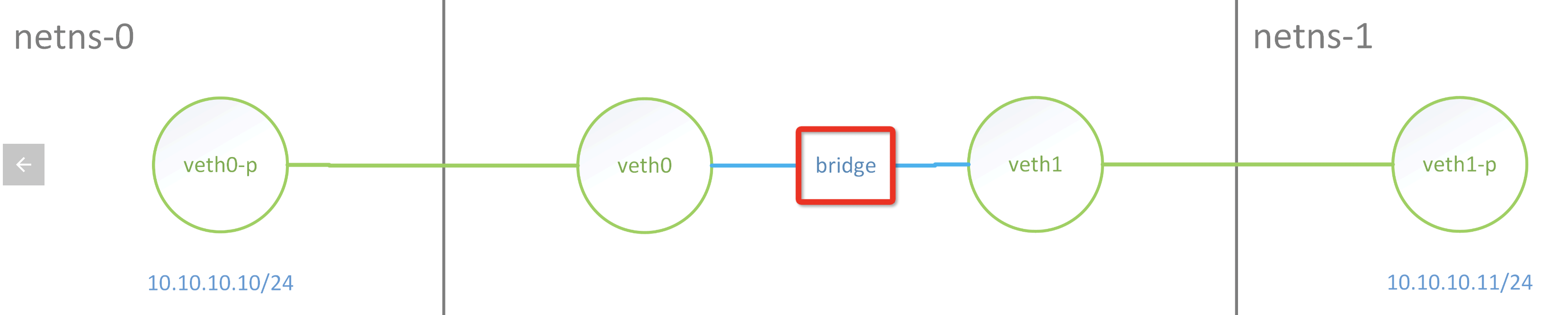
比如如下结构下因为通过xdp redirect来联通veth0、veth1,两边能ping通,但是TCP、UDP 都不通
![[转帖]网络硬件相关知识_网线_04](https://plantegg.github.io/images/951413iMgBlog/image-20220614171759153.png "image-20220614171759153")
正常走bridge ping/tcp/udp是不会有问题的, 这也是docker下常见用法
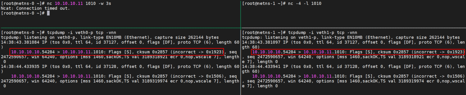
当前主流的网卡(包括虚拟网卡,如veth/tap)都支持一个叫做RX/TX Checksum Offload(RX和TX对应接收和发送两个方向)的特性,用于将传输层协议的校验和计算卸载到网卡硬件中(IP头的检验和会被操作系统用软件方式正确计算)。对于经过启用该功能的网卡的报文,操作系统不会对该报文进行校验和的计算,从而减少对系统CPU资源的占用。
对于没有挂载XDP程序的且开启Checksum Offload功能的Veth设备,在接收到数据包时,会将ip_summed置为CHECKSUM_UNNECESSARY,因此上层L4协议栈在收到该数据包的时候不会再检查校验和,即使是数据包的校验和不正确也会正常被处理。但是若我们在veth设备上挂载了XDP程序,XDP程序运行时将网卡接收队列中的数据转换为结构struct xdp_buff时会丢失掉ip_summed信息,这就导致数据包被L4协议栈接收后由于校验和错误而被丢弃。
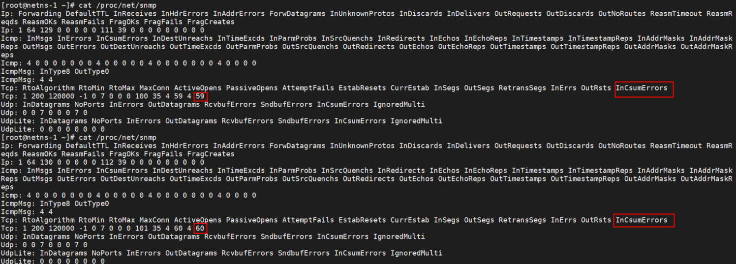
如上图因为veth挂载了XDP程序,导致包没有校验信息而丢掉,如果在同样环境下ping是可以通的,因为ping包提前计算好了正确的校验和
![[转帖]网络硬件相关知识_mac地址_05](https://s2.51cto.com/images/blog/202404/20015221_6622af5541c5d72062.png?x-oss-process=image/watermark,size_16,text_QDUxQ1RP5Y2a5a6i,color_FFFFFF,t_30,g_se,x_10,y_10,shadow_20,type_ZmFuZ3poZW5naGVpdGk= "img")
这种丢包可以通过 /proc/net/snmp 看到
通过命令ethtool -K <nic-name> tx off工具关闭Checksum Offload特性,强行让操作系统用软件方式计算校验和。
日志
sysctl -w net.ipv4.conf.all.log_martians=1 //所有网卡
sysctl -w net.ipv4.conf.p1p1.log_martians=1 //特定网卡

/proc/sys/net/ipv4/conf/eth0.9/log_martians
/var/log/messages中:
messages-20120101:Dec 31 09:25:45 nixcraft-router kernel: martian source 74.xx.47.yy from 10.13.106.25, on dev eth1
修改mac地址
sudo ip link set dev eth1 down
sudo ip link set dev eth1 address e8:61:1f:33:c5:fd
sudo ip link set dev eth1 up
参考资料
https://www.cyberciti.biz/faq/linux-log-suspicious-martian-packets-un-routable-source-addresses/


